
Photos by the author

A recent HO scale kit build of a pair of Pennsylvania Railroad F22 class heavy duty flat cars made me rethink the deck castings and presentation. I had planned to cram lead shot and strips into the nooks and crannies of the underframe, as had been done on a few older resin freight car kits with deep side sills. I did not like that process so my mind wandered. How can weight be added using a simplified effort?
Several years ago, I applied a sheet lead weight to a USRA composite gondola model and covered the lead using a paper print out. The original gondola bottom part was scanned and the printed and trimmed image was laminated to the lead sheet in place of the floor. The combination gave the model a great operating weight and minimized the floor thickness. I decided to try this on the F22 flat cars.

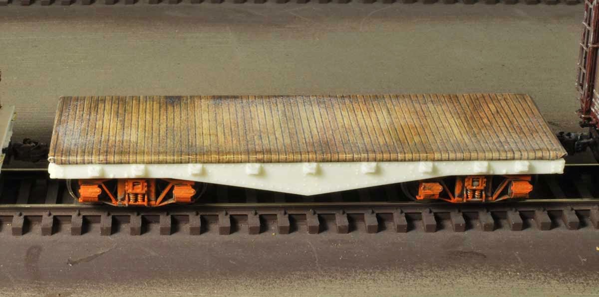
These are nice Funaro & Camerlengo models, but they are pretty light. With trucks and couplers, the basic frame weighs 0.5 ounces without the resin deck casting. A lead sheet trimmed to the deck dimensions weighs 1.3 ounces. Sadly, I only have a cheap, hardly calibrated postal scale. Scientists would laugh at this so these are rough figures. The NMRA recommended weight for this thirty scale foot model is 3.0 ounces. I aim for 75% of the NMRA recommendation. The combined lead sheet and model falls about 0.5 ounces below my 2.25 ounce target. A load may boost the weight in the long term, or some extra can be fit into the underframe cavities. But the lead sheet can minimize the work.
Encouraged by the overall weight addition, I moved forward and prepared a deck casting. A rattle can of light tan color was sprayed onto the deck. A wash of oil-based burnt umber came next then dirt and soot were applied using Pan Pastels and Bragdon powders. The deck was scanned. The lead sheet is 0.047 inches thick, about four HO scale inches. A laminated image will need to wrap around the sides and ends. Using Photoshop, portions of the deck image were copied and pasted to create an image that will overlap the thickness of the lead sheet. This was printed onto glossy photo paper, trimmed, and carefully laminated to the lead using rubber cement.
The edges were not crisp
It looked thick
The corners needed more attention
The deck color looked too new
I agreed with all of their points so work began anew, which was easy since I was building two of the same kit. The second deck was sprayed with primer grey. An oil-based black wash was applied then Pan Pastels and Bragdon powders were used to add grit. Here are the process images for those three stages of work.


The second deck was scanned and manipulated similar to the first attempt. Grey lines were added to mark the boundary of the deck edge and to emphasize that edge. This also helps when folding the image over the lead sheet.
As there were two decks they should not be identical. The first deck scan was used so portions of that deck could be copied and pasted onto a copy of the second deck image. These lighter toned portions of the first deck made it seem like replacement boards had been added. A heavily weathered portion of the second deck image was replaced with a copy of another part of the same deck and rotated. After some nudging of digital image parts, the two decks were ready to print.


Once the print out is laminated to the lead sheet, it needs to be sealed with clear flat. This needs to be done to minimize liquid damage to the print out. The decks are done but they await installation on the car body until after the painting, lettering, and weathering phases are complete. At that point, the hand brake hardware can be installed as well as any hardware for load transportation.
By using a printed laminate, a modeler could make a few different decks for the same flat car body. Portions of different deck images can be substituted onto other deck images to vary the appearance through different print outs. A pair of brass pins mounted in the lead sheet could be keyed to position the deck, enabling an easy change of loads that are secured directly to the deck. I haven't gone this far yet, but it has crossed my mind.
